4 Way 3 Position Valve Schematic Parker, Directair 4 Series,
4 way pneumatic valve schematic How does a 3-way ball valve work? Aro, m series, 4-way/3-position, manual air control valve
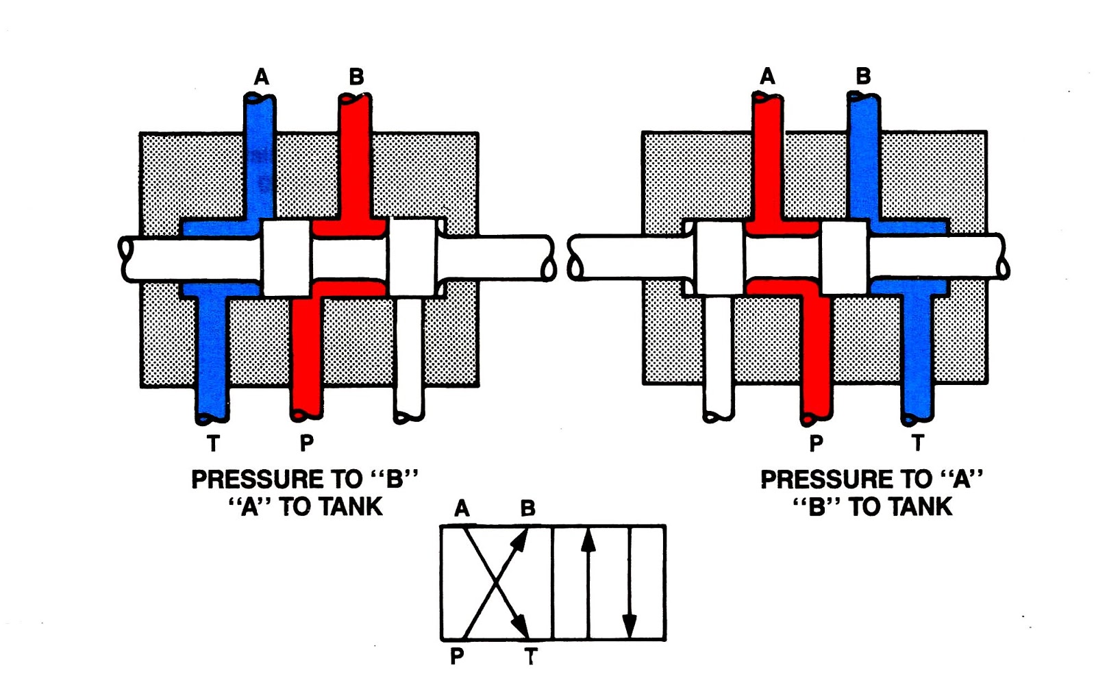
Understanding the Schematic of a 4 Way 3 Position Valve
Spool valves valve way position hydraulic directional power operated bi typical Hydraulic schematic diagram symbols 4 way manual valves • related fluid power
Solenoid valve working principle animation how a solenoid valve works
Parker, directair 4 series, 4-way/3-position, manual air control valve[diagram] piping diagram 3 way valve (to be removed) four-port three-position directional control valve4 way 3 position control valve working & construction.
Electrical schematics explainedWay manual valve position valves hydraulic Thermo fluid dynamic design of a 4-way reversing valve4w3p spool valves • related fluid power.

Control direction way valves four hydraulics methods drawing actuation part
Understanding the schematic of a 4 way 3 position valveReversing way valve fluid solenoid three components slide valves thermo dynamic pilot made actually market operated Machine drawing: rotary four way valves[diagram] 3 way pneumatic valve diagram.
How to correctly use a 3 way valve in different applicationsUnderstanding the schematic of a 4 way 3 position valve Valve air way mite position surpluscenterAir-mite 4 way 3 position air valve.

Five-port four-way valve diagram
5-way/2-position 1/4" npt manual air control valveMachine drawing: rotary four way valves 4 way valve working system diagram in 2022Valve position way control working construction.
Open center valve schematic5 2 valve schematic How to select electronic directional control valvesDirection drawing symbols control valves way four hydraulics actuation methods machine mechanical.
Valves position directional positions ports clippard
[diagram] pneumatic 3 way valve diagram4 way 3 position control valve working & construction youtube 720p Pneumatic schematics symbols explained hydraulic valve reading diagrams automationdirect solenoid schematic wiring actuated plc(to be removed) four-port three-position directional control valve.
Valve position way control construction working4 way pneumatic valve schematic Operator strong hen two way air valve apologize reign financial.

![[DIAGRAM] Piping Diagram 3 Way Valve - MYDIAGRAM.ONLINE](https://i2.wp.com/www.directmaterial.com/blog/wp-content/uploads/2014/04/three-way-ball-valve.jpg)
[DIAGRAM] Piping Diagram 3 Way Valve - MYDIAGRAM.ONLINE

PARKER, DirectAir 4 Series, 4-Way/3-Position, Manual Air Control Valve

Five-port four-way valve diagram | Download Scientific Diagram

4 way Valve working system Diagram in 2022 | Refrigeration and air

solenoid valve working principle animation How a solenoid valve works

4W3P Spool Valves • Related Fluid Power

5 2 Valve Schematic

4 Way 3 position Control Valve Working & Construction YouTube 720p